Simulation & Calculation
Our customers – ranging from small regional companies to international brands – rely on our more than 25 years of expertise in the field of technical product development.
You would like to obtain certainty about your product as early as possible in your development process regarding, for example, sufficient dimensioning, weight saving potential, or NVH? You do not have your own simulation and analysis department or corresponding resources?
We are experts in the field of simulation & calculation and support customers from a wide range of industries to realize their projects, gain safety and reduce costs.
In doing so, we rely on trusting cooperation, open communication and transparent pricing.
Our service portfolio ranges from static and dynamic structural analysis, optimization, fatigue and durability, multi-body dynamics, flow analysis, multidisciplinary analysis to process and manufacturing simulation.
Static structural analysis
Static structural analysis is the standard in simulation and is an important analysis approach for assessing a product across all development steps.
Static structural analyses by means of the finite element method (FEM) are used when a change in the load over time is not present or is negligible from an engineering point of view.
If only certain states are of interest for the technical evaluation of a structure, static analysis assumptions can be applied to dynamically loaded systems.
Linear static finite element analysis (FEA) is used if simplified linear laws regarding, for example, deformations or material represent a sufficiently accurate approximation of the real structure.
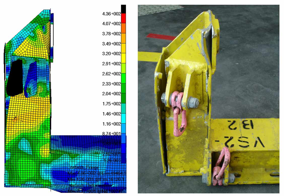
The advantage of linear assumptions lies in short computation times and are thus suitable for extensive variant investigations or calculation of many load cases.
If linear approaches are no longer permissible in the FE model, due to large deformations for instance, further nonlinear definitions for material or contact can be used and the solution is iterative.
With many years of experience in the field of nonlinear analyses, we develop reasonable approximations for structure designs and effective solution methods for an efficient calculation.
- Linear and non-linear (geometric, material, contact) Finite Element Analysis (FEA)
- Complex assembly analysis using nonlinear contacts
- Stability analyses of branching (buckling, tilting and denting) and puncture problems
Dynamic structural analysis
The analysis of oscillations and vibrations is the decisive design criterion for many products – from sensitive constructions such as satellites and the noise development in vehicles to tools and machines.
Vibration problems are usually difficult to assess in advance and often only become apparent while bringing a product into service.
Dynamics, a branch of mechanics, covers structures with time-varying loads and where the vibration behavior is a decisive criterion for component design. In contrast to statics, dynamics therefore also takes into account the time-dependent terms of the general equation of motion.
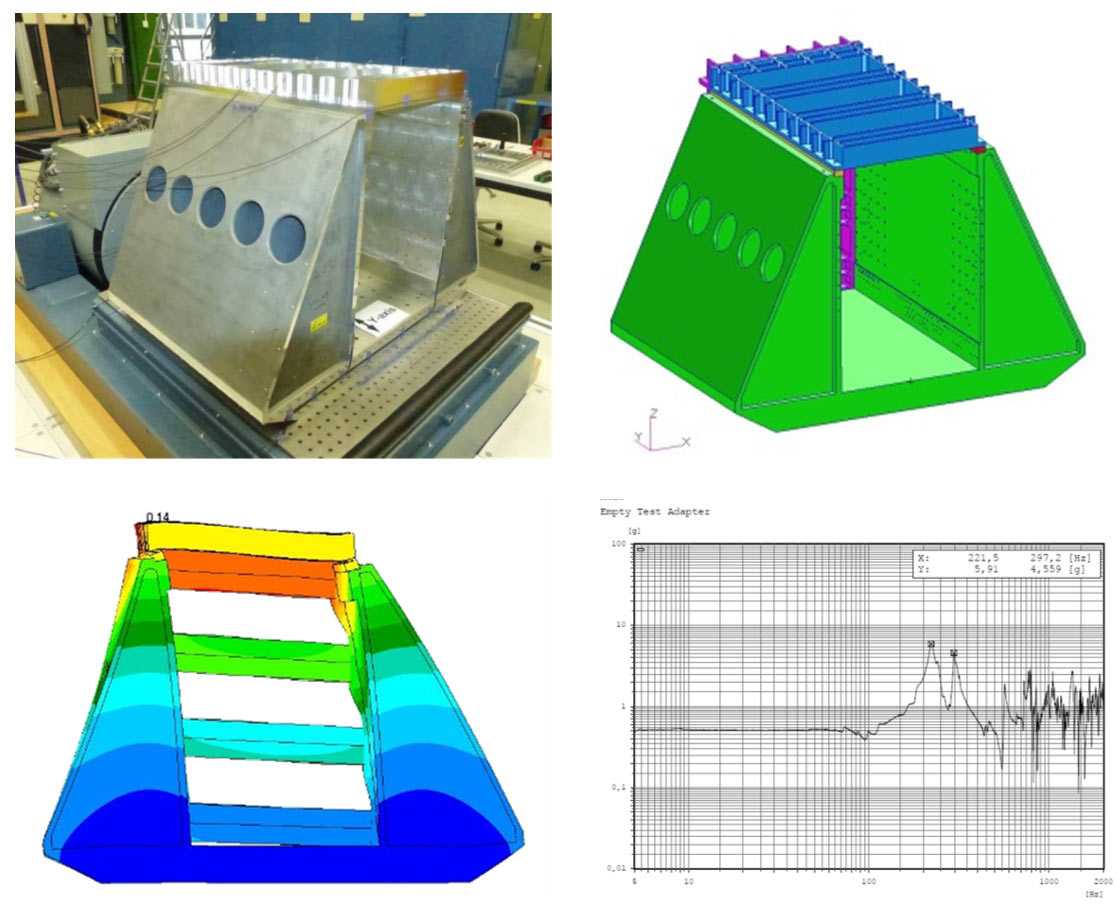
As an alternative to the transient observation in the time domain, there are other FEM calculation methods to analyze the structural response in the frequency domain. Modal analysis can be used, for example, to identify or optimize critical natural frequencies (self-excitation).
- Natural frequency or modal analysis for free, supported as well as prestressed structures
- Transient structural analysis (time-dependent simulation processes)
- Frequency response and response spectrum analysis as well as random analysis (for complex vibration excitations)
Thermal analysis
With increasing demands on load capacity, accuracy and service life, the influence of thermal stress cannot be neglected and must be included in product development. In the field of aviation, engineers consider temperature fluctuations ranging from -50°C to + 70°C, which represents an extraordinary load for mechanical- and as well as electronic components.
The thermal FEM simulation illustrates how the temperature is distributed in individual components or entire assemblies and provides an insight into the resulting heat flows (radiation, conduction and convection). For development, this fully comprehensive insight into thermal processes means the possibility of exploiting optimization potential and identifying problems at an early stage.
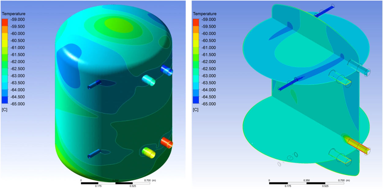
With the help of FEM, we carry out extensive PCB (Plastic Circuit Board) analyses. The analysis can be trimmed to determine peak temperatures of sensitive electronic components, or examine the effectiveness of cooling systems.
- Stationary and transient heat radiation, heat conduction and convection
- Heat generation in electronic components (PCB – Plastic Circuit Board)
- Frictional heat from mechanics
Service life & operational stability
The definition of fatigue strength comes from the field of materials science and describes the calculated service life of a component. The fatigue strength in turn describes the ability of materials and components to withstand static, quasi-static and dynamic loads without damage within the scope of the calculated service life while also considering certain environmental conditions.
The fatigue strength results from a complex interaction of loads from mechanics and the environment, the material, the manufacturing process, and the design or geometric configuration of the component.
Lightweight structures in particular, which in principle are designed to be robust and are subjected to dynamic loads, fail in continuous operation well below the breaking load from the static test.
The design criteria for efficient lightweight structures therefore automatically lead to maximum tolerable operating times, and material fatigue, load peaks or extreme environmental influences lead in the best case to initial damage at the latest after the maximum operating time has been exceeded.
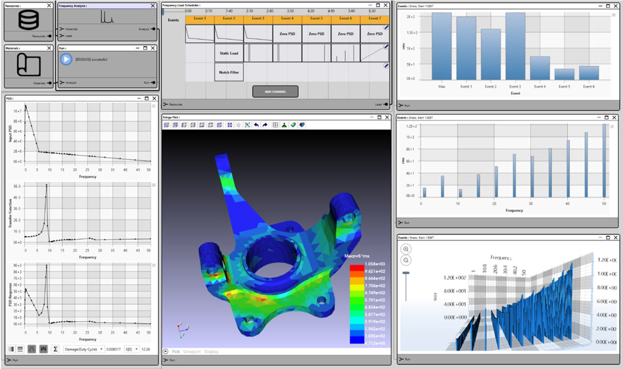
Determining the load limits of a product via classic test runs is therefore usually very time-consuming and cost-intensive due to the above-mentioned complex interrelationships.
We offer as a service the prediction of material fatigue on the basis of the valid regulations of fatigue strength and the use of the recognized methods of analysis with:
- Determination of the service life of components until breakage
- Simulation of crack formation and propagation
- Execution of strength verifications according to FKM, EC and definition of maintenance intervals
Optimization
The approach of “trial and error” is only successful to a limited extent when the number of trials is limited and usually does not lead to an optimal result.
We use software to quickly calculate solutions optimized according to parameters such as the lowest possible weight and stresses or target stiffnesses with the help of intelligent algorithms. The optimization can be applied to isolated requirements from one- or interdisciplinary requirements from severalareas of expertise.
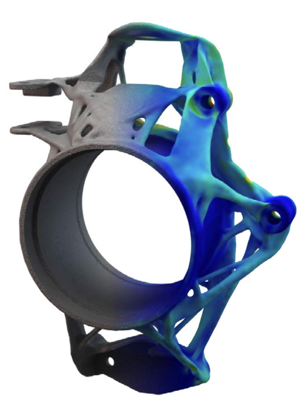
Generative design is a method that offers a highly effective and fast optimization process. During the analysis iterations, the mesh, consisting of voxel elements, is continuously and automatically re-meshed. At the end of the optimization process, printable geometries are generated directly, which can be transferred to common CAD formats without reworking – in the case of classical FE-based methods, the optimized structures must be smoothed with CAD surfaces at the end. This eliminates additional loops via the design department and the focus remains on finding the optimal solution.
Our accompanying strength verification of the optimized structure completes the final design.
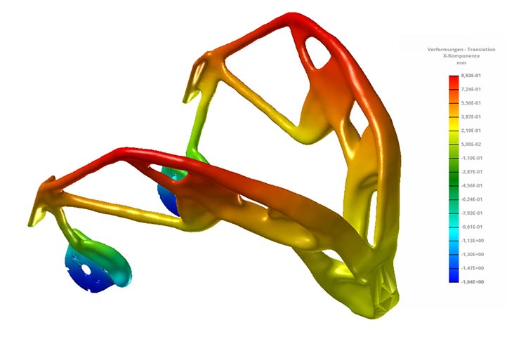
We offer the following three types of optimization:
- Topology optimization: Optimal utilization of the design space (1D, 2D, 3D design spaces) for e.g. cast, milled and printed parts
- Topography optimization: finding the most suitable shape and position of e.g. beads in sheet metal parts
- Free-size optimization: finding optimal thickness distributions in milled parts or layer forms of fiber composite structures
Multi-body dynamics
Multi-body dynamics or multi-body simulation (MBS) is used to calculate loads on moving components in mechanical systems. Here, the components are usually represented as rigid bodies in the form of discrete masses and coupled with each other via contacts, joints, springs and dampers. In addition to displacements, rotations, velocities and accelerations, internal forces, bearing forces and friction forces as well as moments and mass inertias can be determined within the scope of the motion simulation.
The advantage of using the MBS in contrast to the Finite Element Method (FEM), is the representation of complex mechanical systems by means of a small number of degrees of freedom and thus short computation times.
For components whose assumption as a rigid body is not applicable due to the decisive flexibility in the overall system, flexible bodies can be incorporated in the overall system instead.
Depending on the model size as well as the available computer power, these can be integrated either via a modal reduction or directly as a flexible structure in the overall system.
This allows us to simulate complex systems such as chassis (automobile or even aircraft), machines and engines and to make precise statements about the dynamic processes.
- Dynamic simulation of rigid and / or flexible bodies
- Determination of reaction, bearing and friction forces, velocities and accelerations
- Collision and work envelope consideration
Investigation of oscillations and vibrations

Flow simulation (CFD)
Computational fluid dynamics (CFD) is a method for solving the equations governing flow (Navier-Stokes, Euler and/or potential).
CFD simulations are used in a variety of areas such as hydraulics, air flows around small fans or massive rotors, supersonic flows or predictions of geological events such as floods.
CFD simulation is an efficient and cost-effective method for determining a wide variety of flow processes that are otherwise difficult or impossible to verify in tests.
In the case that processes of thermodynamics or mechanics cannot be considered separately from flow, we combine the effects in multiphysics simulations. A common example would be the removal of heat on a printed circuit board by heat conduction of the copper traces and air flow through fans.
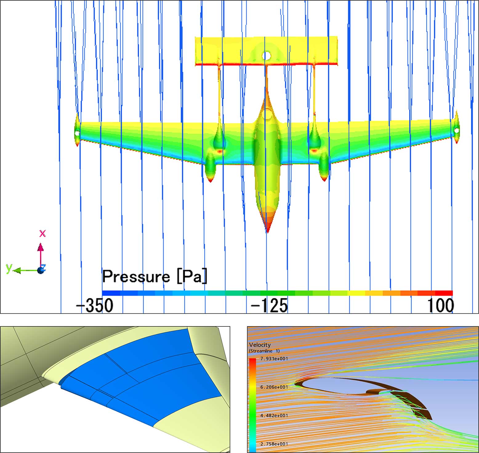
- Internal flows of closed systems (valves or turbines)
- External flows of open systems (rotors, wind turbines, aerodynamics)
- Determination of pressure and velocity distributions, volume and mass flows as well as temperature distributions
Multidisciplinary tasks
The combination of different computational disciplines into a single analysis is often referred to as multiphysics simulation or multidisciplinary simulation. With a combined simulation technique, it is possible to obtain even more accurate results and, above all, to illustrate the existing interactions and their effects. The computational engineer thus gets a much broader view of the system behavior and can thus pursue a holistic optimization strategy.
In consultation with you, we find the most suitable strategy for solving complex physical problems or support you selectively with simulations in your calculation department.
There are almost no limits to multiphysics simulation. Common combinations are:
- Thermal and structural analysis: stress and deformation behavior under high heat exposure (e.g. welding)
- Thermal and flow analysis: heat dissipation on printed circuit boards using fans
- Multibody dynamics and structural analysis: internal forces of an airplane landing gear during landing
- Fluid-Structure Interaction (FSI): Loading of rotor blades by wind flow
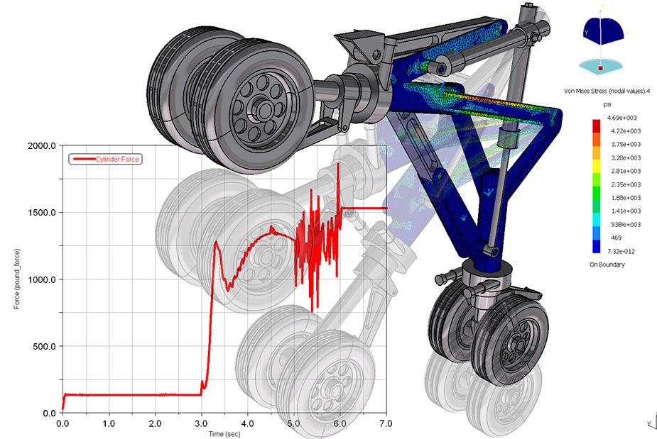
Manufacturing and process simulation
Manufacturing simulation is becoming increasingly important due to modern simulation techniques and ever more powerful hardware and is now established as a standard at major OEMs (original equipment manufacturers). Especially in the case of high quantities, expensive prototypes or production machines, manufacturing simulations carried out in advance offer high cost-saving potentials and help to avoid time-consuming design loops.
Process simulations can be used to improve the production processes (such as forming, printing or welding) in terms of machining times, material consumption or fixture setup itself, as well as the quality of the generated product. Information about manufacturing-related stresses or deformations (including “springback”) can be fed directly back into the design to adjust the design accordingly.
In the case of high volumes, process simulations enable significant savings in machine times and material used.
For low quantities or highly stressed components, simulation helps to get the maximum performance out of the product.
We support 3 manufacturing areas with accompanying simulations:
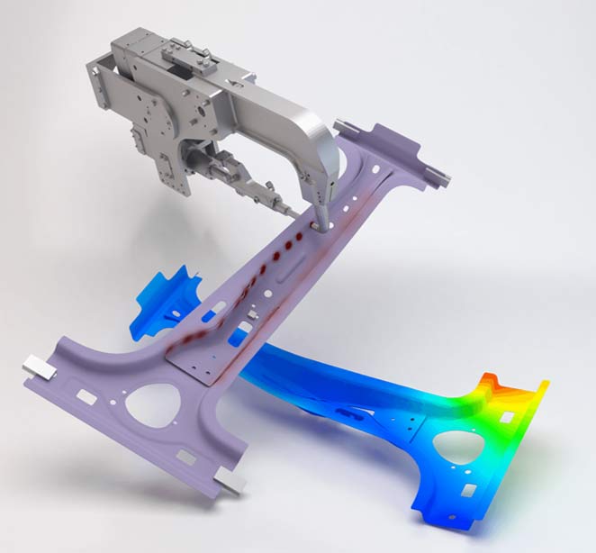
Welding
- Simulation of laser beam, resistance spot, electron beam and arc welding
- Temperature influence ranges over the entire welding process
- Most suitable welding sequence in the assembly
- Structure of the device with clear clamping positions
Forming
- Simulation of forming, cutting or mechanical joining processes
- Reduce tool loads
- Identify defects or weaknesses in the product
- Optimization of aftertreatment processes
Additive
- Simulation of metal-based additive printing processes
- Definition of support structures
- Identification of temperature-induced deformations and stresses
- Precise insights into the entire printing process right up to the cutting process
